Modbus Integration
FX Viewer Modbus Integration Manual
1. Overview
The Modbus TCP server feature links FX Viewer’s real-time acoustic camera data (beam power, alarm status, etc.) with external systems such as PLC, SCADA, and HMI.
With this feature, an external control device such as a PLC can monitor FX Viewer’s camera data and directly control some of its settings.
2. Basic Setup and Connection Details
Automatic Startup
When the FX Viewer application starts, the Modbus server runs automatically. No additional configuration is required.
Connection Details
-
IP Address: The IP address of the PC running FX Viewer
-
Port: 5020 (default) or 502
-
To account for environments without permission to use ports below 1024, the server binds to port 5020 first. If binding to port 5020 fails, the server tries to listen on port 502.
-
On the client side, try connecting to port 5020 first; if the connection fails, try port 502.
-
-
Protocol: Modbus TCP
3. Camera Setup
For the Modbus feature to work correctly, the camera nickname must be set in the expected format.
⚠️ Important: Cameras whose nickname does not follow the rules below are excluded from Modbus integration. This is the most common cause when no data appears, so check it first before integrating.
| Unit ID | Required Nickname | Other Accepted Formats | Device ID |
|---|---|---|---|
| 1 | FX_01 | FX01, FX-01 | 0x4601 |
| 2 | FX_02 | FX02, FX-02 | 0x4602 |
| 3 | FX_03 | FX03, FX-03 | 0x4603 |
-
Nicknames are not case-sensitive. (
fx_01is accepted) -
The same rule applies to the fourth camera and beyond. Unit IDs are assigned in order, one for each camera registered in FX Viewer.
4. Register Map
- Addressing: For PLC and other clients, we recommend using zero-based wire addresses (offsets). (Example: request address 40009 as address
8)
| Modbus Address | Wire Address | Register Name | Data Type | R/W | Description |
|---|---|---|---|---|---|
| 40001 | 0 | DEVICE_ID | U16 | R | Unique device ID (e.g., 0x4601) |
| 40002 | 1 | DEVICE_CONNECTED | U16 | R | Camera connection status (1: connected, 0: disconnected) |
| 40003 | 2 | YEAR | U16 | R | Current time (year) |
| 40004 | 3 | MONTH | U16 | R | Current time (month) |
| 40005 | 4 | DAY | U16 | R | Current time (day) |
| 40006 | 5 | HOUR | U16 | R | Current time (hour) |
| 40007 | 6 | MINUTE | U16 | R | Current time (minute) |
| 40008 | 7 | SECOND | U16 | R | Current time (second) |
| 40009 | 8 | MAX_DBx10 | S16 | R | Maximum sound pressure (dB value x 10), e.g., 45.2dB → 452 |
| 40010 | 9 | ALARM_FLAG | U16 | R | Alarm status (1: alarm active, 0: normal) |
| 40011 | 10 | THRESH_DBx10 | S16 | R/W | Threshold (dB value x 10), e.g., 42.5dB → 425 |
| 40012 | 11 | THRESH_HOLDx10 | S16 | R/W | Hold time (seconds x 10), e.g., 3.5 seconds → 35 |
| 40013-14 | 12-13 | FREQ_LOW_HZ | U32 | R/W | Lower frequency limit (Hz) |
| 40015-16 | 14-15 | FREQ_HIGH_HZ | U32 | R/W | Upper frequency limit (Hz) |
Data Type Settings on the Client
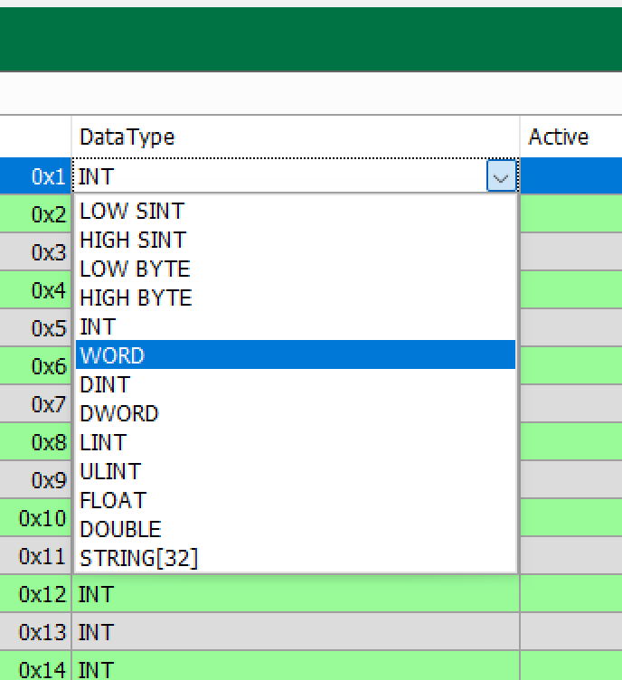
Example of a settings screen in a PLC Modbus client where a data type is selected for each register address. For items that use one register, follow the types in the table above: read signed integers (S16) as INT and unsigned integers (U16) as WORD. Read the two-register (32-bit) FREQ_LOW_HZ and FREQ_HIGH_HZ as a DWORD-family type.
5. Key Features and Usage Examples (Python)
Automatic Trigger Mode Activation
- When the PLC writes a value to the threshold (
40011) or hold time (40012) register, the camera’s recording mode is automatically switched to ‘Trigger Recording’ mode.
⚠️ Caution: Writing to the threshold or hold-time registers has the side effect of changing the camera’s recording mode. If you only need to monitor data, use read requests only, and send write requests only when you intend to switch to trigger recording.
Python Example Code
The example below uses the Python pymodbus library (3.x). Install the library first.
pip install pymodbus💡 Note: pymodbus uses a different keyword for the Unit ID depending on the version. The
slave=in the example below is for 3.x; older versions (2.x) useunit=. Use the keyword that matches your installed version.
from pymodbus.client import ModbusTcpClient
# Set the IP and port of the PC running FX ViewerFX_VIEWER_IP = '127.0.0.1'FX_VIEWER_PORT = 5020
client = ModbusTcpClient(FX_VIEWER_IP, port=FX_VIEWER_PORT)client.connect()
# -- Read data example ---# Read data from camera FX_01 (Unit ID = 1)# Read 2 registers (sound pressure, alarm) starting at wire address 8 (MAX_DBx10)result = client.read_holding_registers(8, count=2, slave=1)
if not result.isError():    max_db_x10 = result.registers[0]    alarm_flag = result.registers[1]
    # Convert to signed 16-bit, then divide by 10    import struct    signed_max_db_x10 = struct.unpack('>h', struct.pack('>H', max_db_x10))[0]
    print(f"FX_01 peak sound pressure: {signed_max_db_x10 / 10.0} dB")    print(f"FX_01 alarm state: {'ALARM' if alarm_flag == 1 else 'normal'}")
# -- Write data example ---# Set the threshold of camera FX_02 (Unit ID = 2) to 45.5 dB# Write the value to wire address 10 (THRESH_DBx10)new_threshold = 45.5threshold_to_write = int(new_threshold * 10)
client.write_register(10, threshold_to_write, slave=2)print(f"FX_02 threshold set request submitted ({new_threshold} dB)")
client.close()
Example Output
Example output when camera FX_01 reads a maximum sound pressure of 45.2 dB (register value 452) and the alarm is in the normal state.
FX_01 peak sound pressure: 45.2 dBFX_01 alarm state: normalFX_02 threshold set request submitted (45.5 dB)6. Troubleshooting
-
If you cannot connect:
-
Verify that the IP address and port (5020) of the FX Viewer PC are correct.
-
Check that Windows Firewall allows port
5020or502through an inbound rule.
-
-
If all data reads as 0:
-
Check that the camera is active in FX Viewer and receiving real-time data.
-
Double-check that the camera’s nickname is set correctly to
FX_01,FX_02, etc. (This is the most common cause.)
-
-
If some values (e.g., frequency) read incorrectly:
- Check that the client’s data type settings match the types in the register map (S16/U16/U32). In particular, the two-register
FREQ_LOW_HZandFREQ_HIGH_HZmust be read as a DWORD-family type. (See the data type settings screen in Section 4.)
- Check that the client’s data type settings match the types in the register map (S16/U16/U32). In particular, the two-register
7. Related Documents
-
Getting Started with the Developer Center — Overview of per-product development documentation tracks
-
Developer Resources — Integration example repositories and external resources